Wednesday, February 19, 2014

Technological Mandalas

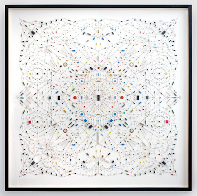
Technological Mandala, the work by Leonardo Ulian. A complex symetry pattern made from electronic components and microchips. It shows contrast between hard cold tech objects in a warm spiritual Hinduism symbol. I personally think it looks like beautiful lace.


Technological Mandala, the work by Leonardo Ulian. A complex symetry pattern made from electronic components and microchips. It shows contrast between hard cold tech objects in a warm spiritual Hinduism symbol.
Technological Mandala No.2, 1912
Electronic components, microchip, wood frame, 120x120 cm

Technological Mandala, the work by Leonardo Ulian. A complex symetry pattern made from electronic components and microchips. It shows contrast between hard cold tech objects in a warm spiritual Hinduism symbol.

Technological Mandala, the work by Leonardo Ulian. A complex symetry pattern made from electronic components and microchips. It shows contrast between hard cold tech objects in a warm spiritual Hinduism symbol.

Technological Mandala, the work by Leonardo Ulian. A complex symetry pattern made from electronic components and microchips. It shows contrast between hard cold tech objects in a warm spiritual Hinduism symbol.

Technological Mandala, the work by Leonardo Ulian. A complex symetry pattern made from electronic components and microchips. It shows contrast between hard cold tech objects in a warm spiritual Hinduism symbol.
 images from leonardoulian

Monday, February 17, 2014

Describe the main energy transformations that take place in a nuclear power station

Power plants that depend on atomic energy don't operate that differently from a typical coal-burning power plant. Both heat water into pressurized steam, which drives a turbine generator. Where the two plants are dissimilar is in the method which is used to heat the water into steam. While a coal-burning power plant burns fossil fuels, nuclear plants depend on the heat that occurs during nuclear fission, when one atom splits into two (see sections 8.4.1 and 8.4.2).
The splitting of a single U-235 atom releases approximately 200 MeV (million electron volts). This may not seem like much, however, a pound of highly-enriched uranium is equal to one million gallons of gasoline. This shows the superior efficiency that nuclear power-production has in comparison to fossil-fuels.
To turn the energy produced through nuclear fission into electrical energy, the energy must be controlled so that it can be effectively and safely used to heat water into steam.
Enriched uranium is typically formed into inch-long (2.5-cm-long) pellets, each with approximately the same diameter as a dime. The pellets are then arranged into long rods, which are then gathered into large bundles. The bundles are submerged in water inside a pressure vessel. The water acts as a coolant, and without it, the uranium would eventually overheat and melt.

Nuclear_Power_Plant.JPG

The uranium bundle acts as an extremely high-energy source of heat. It heats the water and turns it to steam. The steam drives a turbine, which spins a generator to produce power. The diagram above shows the step-by-step process which occurs within a nuclear power plant. Once the water has been heated by the enriched uranium metal, the energy transfers that take place are identical to that within a coal-burning power plant.

Energy Transfers:
- Water is heated by heat energy created through nuclear fission
- Energy is lost to surroundings
- Steam turns a turbine (heat energy transformed into kinetic energy)
- Energy is lost to friction
- Turbine powers a generator
- Energy is lost to friction
- Energy is transformed into electrical energy

Monday, February 3, 2014

Logic Gates

Introduction

Logic gates serve as the building blocks to digital logic circuits using combinational logic. We're going to consider the following gates: NOT gates (also called inverters), AND gates, OR gates, NAND gates, NOR gates, XOR gates, and XNOR gates. We'll also discuss the concept of gate deltay.

NOT gates

NOT gates or inverters have a single bit input and a single bit of output. This is a diagram of a NOT gate. It is a triangle with a circle on the right. The circle indicates "negation".
The truth table defines the behavior of this gate.
  x     z  
0 1
1 0
where x is the input and z is the output.

AND2 gates

AND2 gates have two bits of input and a single bit of output. The subscript, 2, indicates how many inputs this AND gate has. For example, AND3 gates have 3 inputs. The output of AND2 gate is 1 only if both inputs are 1. Otherwise, the output is 0.
The truth table defines the behavior of this gate.
  x1     x0     z  
0 0 0
0 1 0
1 0 0
1 1 1
The function implmented by AND2 gates has interesting properties:
  • The function is symmetric. Thus, x * y == y * x. This can be verified by using truth tables. We use * to represent AND2.
  • The function is associative. Thus, (x * y) * z == x * (y * z). This can be verified by using truth tables.
Because of these properties, it's easy to define ANDn, which is an n-input AND gate.
ANDn(x1, x2,...,xn) = x1 * x2 * ... * xn
That is, an AND gate with n-inputs is the AND of all the bits. This is not ambiguous because the AND function is associative (all parenthesization of this expression are equivalent).

OR2 gates

OR2 gates have two bits of input and a single bit of output. The subscript, 2, indicates how many inputs this OR gate has. For example, OR3 gates have 3 inputs. The output of OR2 gate is 0 only if both inputs are 0. Otherwise, the output is 1.
The truth table defines the behavior of this gate.
  x1     x0     z  
0 0 0
0 1 1
1 0 1
1 1 1
The function implemented by OR2 gates has interesting properties:
  • The function is symmetric. Thus, x + y == y + x. This can be verified by using truth tables. We use "+" to represent OR2
  • The function is associative. Thus, (x + y) + z == x + (y + z). This can be verified by using truth tables.
Because of these properties, it's easy to define ORn, which is an n-input OR gate.
ORn(x1, x2,...,xn) = x1 + x2 + ... + xn
That is, an AND gate with n-inputs is the AND of all the bits. This is not ambiguous because the AND function is associative (all parenthesization of this expression are equivalent).

NAND2 gates

NAND2 gates have two bits of input and a single bit of output. The subscript, 2, indicates how many inputs this NAND gate has. For example, NAND3 gates have 3 inputs. NANDk gates is define unusually. Since NAND2 is not associative, the definition is based on AND2.
In particular
NANDk(x1, x2,...,xn) = NOT( ANDk(x1, x2,...,xn) )
Thus, NANDk is the negation of ANDk.
The truth table defines the behavior of this gate. It's the negation of AND2.
  x1     x0     z  
0 0 1
0 1 1
1 0 1
1 1 0
The function implemented by NAND2 gates has interesting properties:
  • The function is symmetric. Thus, x NAND y == y NAND x. This can be verified by using truth tables.
  • The function is not associative. This can be verified by using truth tables.
Because of these properties, NANDk is defined from ANDk, and not built from NAND2 gates.

NOR2 gates

OR2 gates have two bits of input and a single bit of output. The subscript, 2, indicates how many inputs this OR gate has. For example, NOR3 gates have 3 inputs. The output of NOR2 gate is the negation of OR2.
The truth table defines the behavior of this gate.
  x1     x0     z  
0 0 1
0 1 0
1 0 0
1 1 0
The function implmented by NOR2 gates has interesting properties:
  • The function is symmetric. Thus, x NOR y == y NOR x. This can be verified by using truth tables.
  • The function is not associative. This can be verified by using truth tables.
Because of these properties, NORk is defined from ORk, and not built from NOR2 gates.

XOR2 gates

XOR2 gates have two bits of input and a single bit of output. The output of XOR2 gate is 1 only if the inputs have opposite values. That is, when one input has value 0, and the other has value 1.. Otherwise, the output is 0.
This is called exclusive-or. The definition of OR2 is inclusive-or, where the output is 1 if either input is 1, or if both inputs are 1.
XOR2 can be defined using AND2, OR2, and NOT.
x XOR y == ( x AND (NOT y) ) OR ( (NOT x) AND y ) == x\y + y\x
Here's a diagram of the XOR2 gate.

If you look carefully at the drawing of the gate, there is a second arc behind the first one near the inputs. Since this second arc is hard to see, it's usually a good idea to write the word "XOR" inside the gate.
The truth table defines the behavior of this gate.
  x1     x0     z  
0 0 0
0 1 1
1 0 1
1 1 0
The function implmented by XOR2 gates has interesting properties:
  • The function is symmetric. Thus, x (+) y == y (+) x. This can be verified by using truth tables. (We use (+) to denote logical XOR--ideally, we'd draw it with a + sign inside a circle, but HTML doesn't seem to have a symbol for this).
  • The function is associative. Thus, [ x (+) y ] (+) z == x (+) [ y (+) z ]. This can be verified by using truth tables.
Because of these properties, it's easy to define XORn, which is an n-input XOR gate.
XORn(x1, x2,...,xn) = x1 (+) x2 (+) ... (+) xn
That is, an XOR gate with n-inputs is the XOR of all the bits. This is not ambiguous because the XOR function is associative (all parenthesization of this expression are equivalent).

XNOR2 gates

XNOR2 gates have two bits of input and a single bit of output. The output of XNOR2 gate is the negation of XOR2 and has 1 when both inputs are the same.
If you look carefully at the drawing of the gate, there is a second arc behind the first one near the inputs. Since this second arc is hard to see, it's usually a good idea to write the word "XNOR" inside the gate.
The truth table defines the behavior of this gate.
  x1     x0     z  
0 0 0
0 1 1
1 0 1
1 1 0
The function implmented by XNOR2 gates has interesting properties:
  • The function is symmetric. Thus, x XNOR y == y XNOR x. This can be verified by using truth tables.
  • The function is associative. Thus, (x XNOR y) XNOR z == x XNOR (y XNOR z). This can be verified by using truth tables.
Because of these properties, it's easy to define XNORn, which is an n-input XNOR gate.
XNORn(x1, x2,...,xn) = x1 XNOR x2 XNOR ... XNOR xn
That is, an XNOR gate with n-inputs is the XNOR of all the bits. This is not ambiguous because the XNOR function is associative (all parenthesization of this expression are equivalent).
(Error-checkers! You may wish to verify this, and email me if this is incorrect!).

Building Blocks

We can use logic gates to build circuits. While we've described 6 gates, you can do with only three gates to build all possible circuits: AND2, OR2, and NOT. In fact, you don't even need all three gates. It can be done in two kinds of gates of less. We'll explain in a future section. These circuits can implement any truth table.

Valid Combinational Circuits

The inverse is not true. Not every circuit that is built from gates corresponds to a truth table. In particular, you must observe the following rules if it's to correspond to a truth table.
  • The output of a gate may only be attached to the input of another gate. (Think of this as a directed edge from output to input).
  • There must be no cycles in the circuit. Treat the circuit like a directed graph with directed edges defined in the previous item.
  • Although the output of a gate may be attached to more than one input, an input may not have two different outputs attached to it (this would create conflicting input signals).
  • Each input of a gate must come from either the output of another gate or a source. A source is a source that generates either a 0 or 1.

Gate Delay

Real gates have delay. In other words, if you change the value of the inputs, say from 0 and 0 to 0 and 1, then the output takes some small amount of time before it changes. This delay is called gate delay. This delay is due to the fact that information can travel at most, the speed of light, and in reality, the time it takes to do the computation is not infinitely quick.
This delay limits how fast the inputs can change and yet the output have meaningful values. It also allows certain kinds of circuits to be created that don't follow the rules from the previous section. In particular, flip flops (to be discussed later) can be generated from gates that use cycles.

Why Subscripts?

Most books don't distinguish between an AND2 gate and a AND3 gate. They claim an AND gate is an AND gate, regardless of the number of inputs. While this is true, I subscript it because an AND2 and an AND3 do not have the same truth table. In particular, an AND2 truth table has 4 rows while an AND3 has 8. While the two truth tables are related, they still define different functions.
Thus, I make the distinction by subscripting the number of inputs.

Summary

Logic gates are the building blocks of combinational logic circuits. You can buy logic gates from electronic hobby places. These gates are primarily for hobbyists. Each chip usually has about 4 logic gates. Real computers don't use these kinds of gates, because they take far too much space. With VLSI technology, you can cram millions of gates onto a wafer no bigger that your thumbnail.
The behavior of logic gates can be described by truth tables. However, because these gates are "physical", they have some properties not expressed in truth tables. In particular, gate delay describes the amount of time it takes for the output to change when the input changes. This time is not zero, thus, one must wait a short amount of time for the output to take effect.
We'll discuss how to build circuits from these gates in a later set of notes.
Friday, January 24, 2014

Direct-Current Motor Principles

Direct-Current Motor Principles

Magnetic lines of force flow from the north pole to the south pole
FIGURE. Magnetic lines of force flow from the north pole to the south pole.
DC motors use the interaction of magnetic fields to convert the electrical energy into mechanical energy. Magnetic lines of force flow from the north pole to the south pole of a magnet. If a current-carrying conductor is placed within the magnetic field, two fields will be present. On the left side of the conductor, the lines of force are in the same direction. This will concentrate the flux density of the lines of force on the left side. This will produce a strong magnetic field because the two fields will reinforce each other. The lines of force oppose each other on the right side of the conductor. This results in a weaker magnetic field. The conductor will tend to move from the strong field to the weak field. This principle is used to convert electrical energy into mechanical energy in a starter motor by electromagnetism.
Interaction of two magnetic fields
FIGURE. Interaction of two magnetic fields.
Conductor movement in a magnetic field
FIGURE. Conductor movement in a magnetic field.
A simple electromagnet-style starter motor is shown. The inside windings are called the armature. The armature is the moveable component of the motor that consists of a conductor wound around a laminated iron core. It is used to create a magnetic field. The armature rotates within the stationary outside windings, called the field coils, which has windings coiled around pole shoes. Field coils are heavy copper wire wrapped around an iron core to form an electromagnet. Pole shoes are made of high-magnetic permeability material to help concentrate and direct the lines of force in the field assembly.
Simple electromagnetic motor
FIGURE. Simple electromagnetic motor.
When current is applied to the field coils and the armature, both produce magnetic flux lines. The direction of the windings will place the left pole at a south polarity and the right side at a north polarity. Hie lines of force move from north to south in the field. In the armature, the flux lines circle in one direction on one side of the loop and in the opposite direction on the other side. Current will now set up a magnetic field around the loop of wire, which will interact with the north and south fields and put a turning force on the loop. This force will cause the loop to turn in the direction of the weaker field. However, the armature is limited in how far it is able to turn. When the armature is halfway between the shoe poles, the fields balance one another. The point at which the fields are balanced is referred to as the static neutral point.
Field coil wound around a pole shoe
FIGURE. Field coil wound around a pole shoe.
Rotation of the conductor is in the direction of the weaker field
FIGURE. Rotation of the conductor is in the direction of the weaker field.
For the armature to continue rotating, the current flow in the loop must be reversed. To accomplish this, a split-ring commutator is in contact with the ends of the armature loops. The commutator is a series of conducting segments located around one end of the armature. Current enters and exits the armature through a set of brushes that slide over the commutator’s sections. Brushes are electrically conductive sliding contacts, usually made of copper and carbon. As the brushes pass over one section of the commutator to another, the current flow in the armature is reversed. The position of the magnetic fields are the same. However, the direction of current flow through the loop has been reversed. This will continue until the current flow is turned off.
Starter armature
FIGURE. Starter armature.
Starter and solenoid components
FIGURE. Starter and solenoid components.

Armature

Lamination construction of a typical motor armature
FIGURE. Lamination construction of a typical motor armature.
The armature is constructed with a laminated core made of several thin iron stampings that are placed next to each other. Laminated construction is used because, in a solid iron core, the magnetic fields would generate eddy currents. These are counter voltages induced in a core. They cause heat to build up in the core and waste energy. By using laminated construction, eddy currents in the core are minimized.
The slots on the outside diameter of the laminations hold the armature windings. The windings loop around the core and are connected to the commutator. Each commutator segment is insulated from the adjacent segments. A typical armature can have more than 30 commutator segments.
A steel shaft is fitted into the center hole of the core laminations. The commutator is insulated from the shaft.
Lap winding diagram
FIGURE. Lap winding diagram.
Two basic winding patterns are used in the armature: lap winding and wave winding. In the lap winding, the two ends of the winding are connected to adjacent commutator segments. In this pattern, the wires passing under a pole field have their current flowing in the same direction.
Wave-wound armature
FIGURE. Wave-wound armature.
In the wave-winding pattern, each end of the winding connects to commutator segments that are 90 or 180 degrees apart. In this pattern design, some windings will have no current flow at certain positions of armature rotation. This occurs because the segment ends of the winding loop are in contact with brushes that have the same polarity. The wave-winding pattern is the most commonly used due to its lower resistance.

Field Coils

The field coils are electromagnets constructed of wire ribbons or coils wound around a pole shoe. The pole shoes are constructed of heavy iron. The field coils are attached to the inside of the starter housing. Most starter motors use four field coils. The iron pole shoes and the iron starter housing work together to increase and concentrate the field strength of the field coils.
Field coils mounted to the inside of starter housing
FIGURE. Field coils mounted to the inside of starter housing.
When current flows through the field coils, strong stationary electromagnetic fields are created. The fields have a north and south magnetic polarity based on the direction the windings are wound around the pole shoes. The polarity of the field coils alternate to produce opposing magnetic fields.
Magnetic fields in a 4-pole starter motor
FIGURE. Magnetic fields in a 4-pole starter motor.
In any DC motor, there are three methods of connecting the field coils to the armature: in series, in Darallel (shunt), and a comDound connection that uses both series and shunt coils.

Wednesday, January 22, 2014

Principle of Alternator

Principle :
    A.C. generators or alternators (as they are usually called) operate on the same fundamental principles of electromagnetic induction as D.C. generators.
    Alternating voltage may be generated by rotating a coil in the magnetic field or by rotating a magnetic field within a stationary coil. The value of the voltage generated depends on-
                     the number of turns in the coil.
                     strength of the field.
                     the speed at which the coil or magnetic field rotates.